
Powering Technologies For Network Devices
An Examination of Use, Familiarity, and Interest
Part 1 of a 3-part Series
When running or testing cabling in a data center, it’s always a good idea to understand the cable plant architecture. This knowledge helps a field technician to understand how data flows within and between application servers and storage devices. Depending on the plant design, cable length and types/numbers of network infrastructure equipment will differ. Knowing this will speed up the process of pulling and/or testing new cables in an area of the network where performance and reliability are paramount.
Unlike in-building and campus-wide cable plants that commonly use similar cabling layouts, three distinct plant designs dominate the data center. Let’s look at each design, the type of cabling that’s commonly deployed and what to expect from a cable deployment and testing perspective.
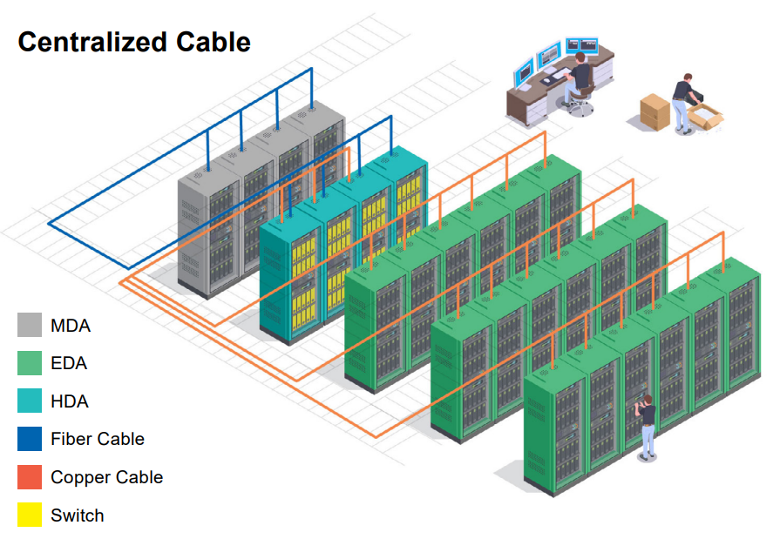
1. Centralized Cable Plants
If working in small or older data centers, you’re likely to run into a centralized cable plant design. The best way to tell if a data center uses a centralized design is when all cabling is pulled to a single location as shown in the following diagram:
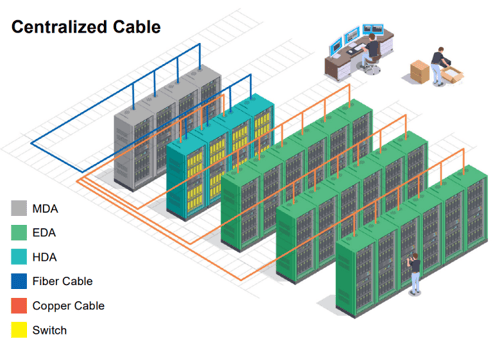
While the centralized cable plant design is the easiest to grasp as all cabling is pulled to one area in the data center, there are some notable drawbacks. For one, the sheer amount of cabling that’s pulled to a single spot can quickly overwhelm overhead or under-floor cable trays and paths. It also makes it incredibly difficult to remove/replace cabling when it comes end of life. Thus, what often ends up happening is a jumble of new and old cabling will occupy the same space that creates confusion as to which cable will be optimal from a performance and reliability standpoint. This is precisely where cable test equipment that can quickly validate transport capabilities of copper/fiber cabling for both Ethernet and fibre channel use is so critical.
2. End-of-Row (EoR) Cable Plants
To address cabling overload found in centralized cable plant designs, a modern approach to data center layouts is to disaggregate network access switches and place them at the end-of-row (EoR). Thus, instead of all cabling being run back to a single centralized location, servers first connect to an intermediary EoR switch. The distributed switches then connect to centralized distribution data center switches via fiber cabling that are responsible for inter-row and for communicating with users/devices throughout the corporate LAN. The following diagram depicts rows of servers connecting to distributed EoR switches that uplink to a centralized data center distribution switch block.
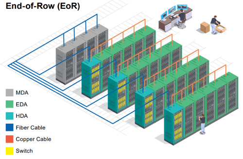
While EoR cable plant designs help alleviate cable glut in a single location, note that depending on the size of the data center row, cable congestion can still occur at the networking rack. Compounding this problem is the proliferation of data center specific IoT sensors that are being deployed in and around the facility. This includes surveillance cameras, door controllers and various sensors that monitor data center temperature and humidity. Additionally, a healthy mixture of twisted-pair copper and fiber optic cabling is far more likely to be found. Thus, it’s important that those testing/troubleshooting cabling in EoR data centers have tools that can quickly switch between the testing of copper and fiber. AEM’s modular design makes it convenient for operations staff to be able to test for a multitude of cabling and connector types using a single test tool.
3. Top-of-Rack (ToR) Cable Plants
The most modern and distributed data center cable layout to date is known as the top-of-rack (ToR) design. Here, every rack is installed with an access switch that only services connectivity to servers in that specific rack. From there, the ToR switches connect to a centralized distribution block of switches similar to the EoR design. The main benefit of ToR verses EoR resides in the fact that cable lengths from servers to the ToR access switches are very short and eliminate any and all cabling congestion. The caveat is that many more switches are required in the data center, adding to complexity and cost. The following diagram shows an example of a ToR designed data center.
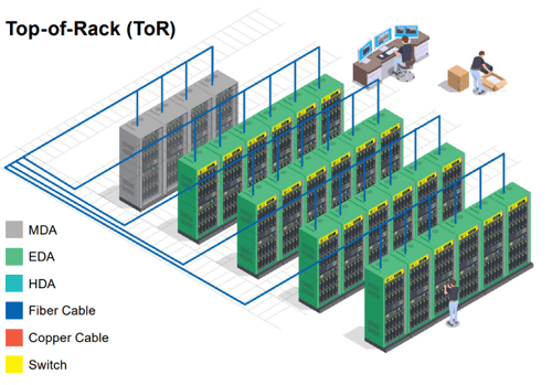
Problems with ToR designs often arise when NetOps administrators get complacent and begin connecting servers to ToR switches that are in adjacent racks. This sometimes happens when a ToR switch fills up in one rack – but free ports are available in adjoining racks. Instead of doing the right thing and adding extra port capacity to a fully-consumed rack, cabling is instead run to a nearby rack. From a troubleshooting perspective, this complicates matters as cabling may have to be manually traced back to understand which ToR switch a server is connect to.
In these situations, a tool to quickly identify the switch name and type that a cable is connected to is advantageous. Both the TestPro and NSA offer a series of network test features that are useful for troubleshooting data center cabling issues. One such tool feature is the ability to connect a TestPro/NSA into the remote end of a copper for fiber run. Using LLDP or CDP, the test tool identifies and displays useful switch detail information such as the switch name, port number, VLAN ID, manufacturer, model and management IP address. This information can be used to quickly verify what ToR switch the cable is connected to, eliminating the need to manually trace them.
Ready to learn more about how AEM's award-winning test solutions can help you achieve your cable testing needs? Request a demo with our team.

An Examination of Use, Familiarity, and Interest

Looking at the challenges of a typical Internet of Things (IoT) rollout, the biggest hurdle usually...
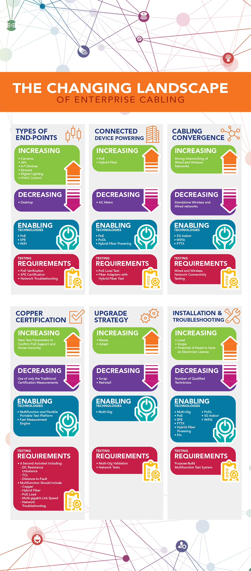
Enterprise cabling systems are going through a big paradigm shift. In the past, one of the main...
Leave a comment