

Powering Technologies For Network Devices
An Examination of Use, Familiarity, and Interest
Power over Ethernet (PoE) and power over data line (PoDL) are becoming increasingly popular energy delivery mechanisms for network devices. Due to the rise in PoE and PoDL demand – combined with changing power requirements — things are becoming more complicated from a cabling perspective. What once was an area of structured cabling that required little understanding has blossomed into a discipline containing multiple standards and options to consider. In this article, we’re going to cover power over network capabilities, power delivery standards and cabling considerations to make when planning for a PoE or PoDL deployment.
PoE/PoDL source and endpoint capabilities
The beauty of powering network devices through copper cabling is that they no longer require direct access to an electrical outlet for deployment. Instead, the network cabling performs both power and data transport functions across a single cable. This technology significantly reduces cost and simplifies the deployment of networked devices in areas where power may not be available.
That said, the amount of wattage required to power an endpoint can vary greatly depending on what purpose each device serves. Additionally, the power delivery capabilities of the power delivery source will differ in terms of the maximum wattage delivered out each switch port. When a device that is PoE- or PoDL-capable is connected to a switch, midspan or injector that can deliver power, the power source and endpoint will automatically negotiate a wattage amount needed to power the device based on an industry standard. Most powered devices and PoE/PoDL switches/midspans/injectors adhere to one of several IEEE standards for power negotiation and delivery over twisted pair cabling. Here are five of the most popular standards available today.
802.3af
IEEE 802.3af became a standard in 2003. It is also commonly referred to as Type 1 power – or simply PoE. 802.3-capable Ethernet switches or midspans/injectors can send up to 15.4 W of power over standard 4-pair twisted cabling of CAT5 or above. Yet, because power loss will occur over copper wiring, this standard only guarantees 12.95 W of power to an endpoint up to 100 meters in length.
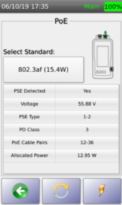
IEEE 802.3af Test Results
The 802.3af standard uses two of four twisted pairs in an Ethernet cable for power delivery. For 10 and 100BASE-T Ethernet, power is sent across the two unused pairs not being used for data communication. For 1000BASE-T and higher Ethernet — which uses all four pair of wires for data transport — 802.3af still uses only two pairs. The difference is that a common-mode voltage is added to these pairs. The common-mode voltage is then sent across the pairs and consumed at the endpoint during normal operation. The remaining voltage then interpreted by the endpoint as standard data communications.
802.3at
As interest in PoE-capable devices grew, so did the need to deliver more power across the wire. This is the primary reason for IEEE 802.3at – which was standardized in 2009. 802.3at is also known as Type 2 power – or PoE+. Like 802.3af, this standard only uses two pair of wires for power delivery. However, it can send up to 30 W of power. Because of loss, this standard guarantees up to 25.5 W to the endpoint.
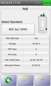
IEEE 802.3at Test Results
802.3bt
The latest IEEE standard for 4 pair Ethernet is 802.3bt. Unlike previous standards that only use two of the four pairs of a Category 5e or higher cable, 802.3bt uses all 4 pair for power delivery. Within this single standard, there are two versions available. The first is also known as Type 3 PoE. It delivers 60 W on the wire – 51 of which are available to the endpoint. The other is Type 4 PoE. This version of he 802.3bt standard delivers up to 90 W of power – 81 guaranteed to the end device.
SPE and 802.3bu
One of the major problems inherent with the Internet of Things (IoT) movement is that it often requires a considerable amount of new cabling to be run. This cabling may be deployed in areas where space and weight of the cable plant is a major concern. The new IEEE 802.3cg Ethernet standard uses only a single pair for data transport. That’s why it’s often referred to as single pair Ethernet (SPE). SPE is a cheaper, smaller and lighter alternative to more typical 4 pair Ethernet cables. It caters toward enterprise IoT, industrial IoT (IIoT) and modern automotive cabling deployments. Coexisting with 802.3cg is the 802.3bu standard which is also called power over data line – or PoDL. Within this standard are 10 different power classes that sends 0.566 to 65.3 W of power across the pair and delivering between 0.5 to 50 W to the end device.
Things to keep in mind when planning for any PoE or PoDL deployment
When planning a cabling project that requires powering devices across the network, there are four key questions that must be asked:
Ready to learn more about how AEM's award-winning test solutions can help you achieve your cable testing needs? Request a demo with our team.

An Examination of Use, Familiarity, and Interest
-1.png)
Part 2 of a 3-part Series This is part 2 of a 3-part series. To view Part 1, Common Data Center...

Part 3 of a 3-part Series This is part 3 of a 3-part series. To view the previous 2 parts, click...
Leave a comment